주메뉴


Product
리니어 모터
홈 > 리니어모터 > 드라이버 > Servotronix CDHD2 제품
Servotronix CDHD2 제품
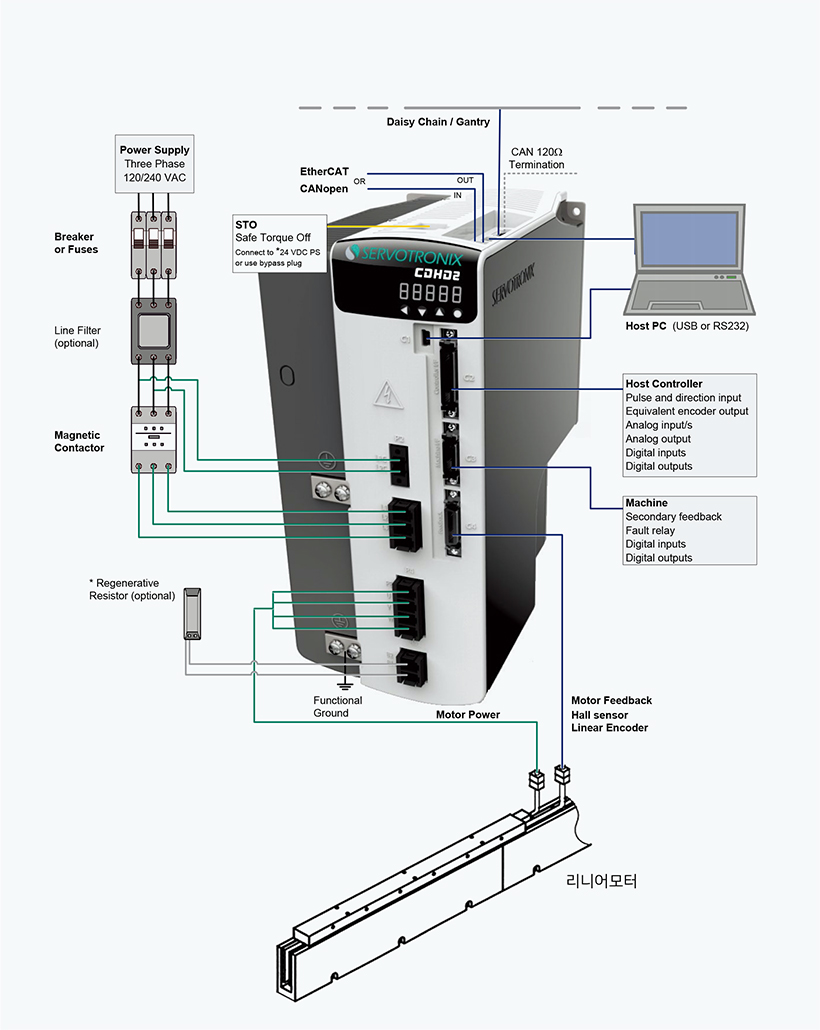
시스템 구성
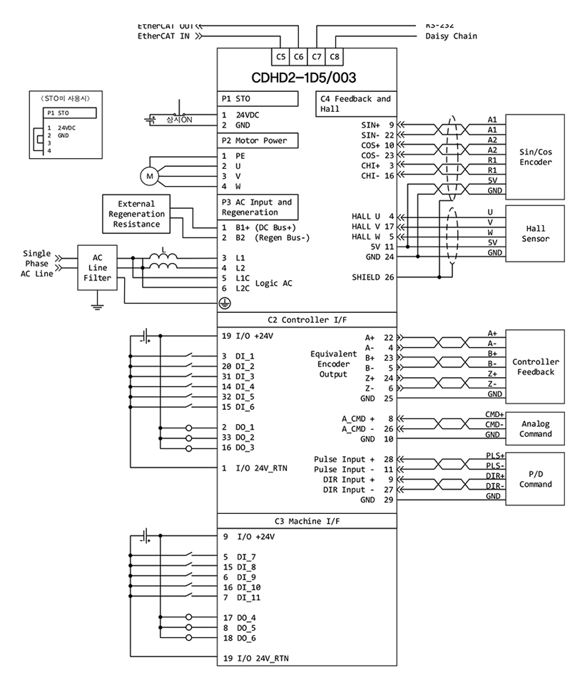
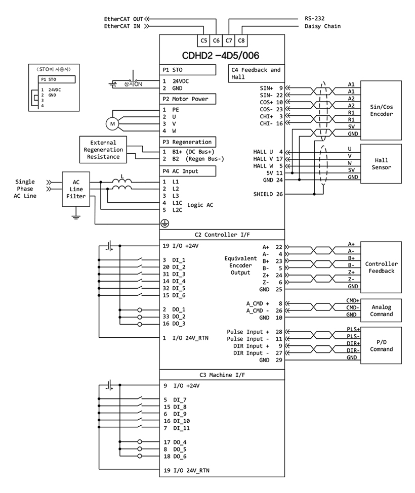
SIN/COS Type Encoder 적용 시 결선도
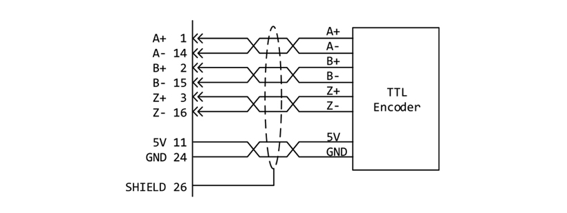
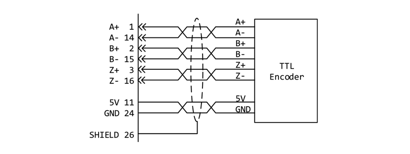
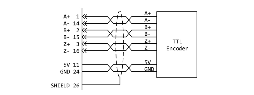
TTL Type Encoder 적용 시 결선도(C4)
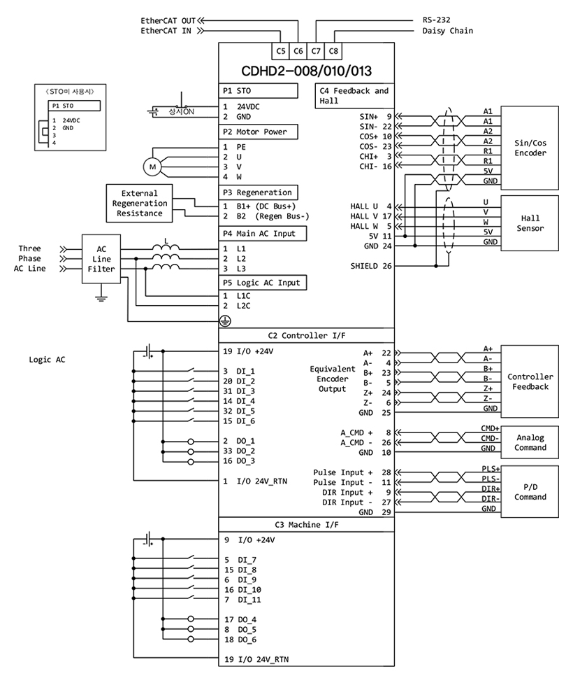
SIN/COS Type Encoder 적용 시 결선도
TTL Type Encoder 적용 시 결선도(C4)
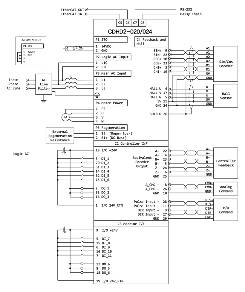
SIN/COS Type Encoder 적용 시 결선도
TTL Type Encoder 적용 시 결선도(C4)

SIN/COS Type Encoder 적용 시 결선도
TTL Type Encoder 적용 시 결선도(C4)
엔코더 피드백 사양
| Feature | Specification | |
|---|---|---|
| Power Supply | Supply Voltage from Drive | 5 VDC (8 VDC*) |
| Max. Supply Current from Drive to Primary Encoder** |
320 mA @5V 140 mA @8V |
|
| Cable | Max. Length | 50 m for sensAR encoder. For other feedback devices, per device specifications |
| Incremental Encoder | Differential RS422 or RS485 | AqB with or without index, 8-channel Tamagawa |
| AqB Max. Input Frequency | 5 MHz (before quadrature) | |
| Min. Index Pulse Width | 1 μs | |
| Hall Sensor | Signal | Open collector single-ended (optional differential) |
| Resolver | Signal | Sine/cosine differential |
| Transformation Ratio | 0.45 - 0.8 | |
| Excitation Frequency | 8 kHz | |
| Input Voltage from Drive | 6 - 22 Vpp | |
| Max. DC Resistance | 120 Ω (stator) | |
| Max. Drive Current | 55 mA rms | |
| Output Voltage to Drive | 10 Vpp | |
| Sine Encoder | Signal | Sine/cosine differential, with or without Halls |
| Signal Level | 1 Vpp @ 2.5 V | |
| Max. Input Frequency | 300 kHz | |
| Protocols | EnDat 2.1, HIPERFACE | |
| Input Impedance | 120 Ω | |
| Interpolation | Up to 16384 (14 bit) | |
| SSI Encoder | Signal | Differential data and clock for synchronous encoders Data only for asynchronous encoders |
| Protocols | sensAR, EnDat 2.2, BiSS-C (up to 26 bit), Nikon, Tamagawa | |
| Motor Temperature | Signal | Thermal resistor PTC or NTC, User-defined fault threshold |
* Some features are not available on all models
Check the options in the section Ordering Information, or contact your supplier.
| SIN-COS 최대 입력 주파수 : 300kHz | - 40 ㎛ sin-cos encoder 사용시 최대 속도 12m/s 구동가능 - 20 ㎛ sin-cos encoder 사용시 최대 속도 6m/s 구동가능 |
|---|---|
| A/B상 엔코더(Digital Encoder) 최대 입력 주파수(체배 후 ) : 16MHz |
- 0.1 ㎛ A/B상 엔코더 사용시 최대 속도 최대 속도 1.6m/s 구동가능 - 0.5 ㎛ A/B상 엔코더 사용시 최대 속도 최대 속도 3.2m/s 구동가능 - 1.0 ㎛ A/B상 엔코더 사용시 최대 속도 최대 속도 16m/s 구동가능 |
드라이브 사양
| Model CDHD2- | 1D5 | 003 | 4D5 | 006 | 008 | 010 | 013 | 020 | 024 | ||
|---|---|---|---|---|---|---|---|---|---|---|---|
| Output Current | Continuous[Arms] | 1.5 | 3 | 4.5 | 6 | 8 | 10 | 13 | 20 | 24 | |
| Peak[Arms] | 4.5 | 9 | 18 | 18 | 28 | 28 | 28 | 48 | 48 | ||
| Driver Size(W X H X D) (mm) | 43.2 x 157.67 x 144.71 | 55.24 x 157.59 x 164.5 | 62.18 X 177.3 X 174.88 | 117.8x245.2x193.5 | |||||||
| Control Circuit Power Supply |
Voltage, Frequency Phase | 1 Phase 120/240VAC, 50/60Hz | |||||||||
| Main Circuit Power Supply |
Phase | 1 Phase | 1/3 Phase | 3 Phase | |||||||
| Voltage, Frequency | 120/240VAC, 50/60Hz | ||||||||||
| Position Control | Input/Output | Position command / Velocity command | |||||||||
| Performance | Update rate 250 ㎲ (4kHz) | ||||||||||
| Control loop | PID and feed-forward | ||||||||||
| Reference Command | Pulse and direction with electronic gearing, Serial, Serial RS232 or USB*, CANopen* | ||||||||||
| Velocity Control | Input/Output | Velocity command / Current command | |||||||||
| Performance | Update rate 125 ㎲ (8kHz) | ||||||||||
| Selectable velocity Control Loops |
PI , PDFF, Standard pole placement, Advance pole placement, Standard pole placement high frequency, Pole placement with active dumping |
||||||||||
| Filters | First order low pass filter, Double first order low pass filter, Notch, High pass filter, Band pass filter, User defined polynomial filter |
||||||||||
| Reference Command | Analog Voltage ±10VDC, Serial RS232 or USB*, CANopen* | ||||||||||
| Torque Control | Input/Output | Current command / 3 phase PWM command | |||||||||
| Performance | Update rate 31.25㎲ (32kHz), Output waveform sinusoidal | ||||||||||
| Step Response Time | Actual current reaches command in two cycles, 62.5㎲ | ||||||||||
| Control loop | DQ, PI, Feed-forward | ||||||||||
| Reference Command | Analog Voltage ±10 VDC, Serial RS232 or USB*, CANopen* | ||||||||||
| Autotuning | Automatic self-tuning of current control loop parameters | ||||||||||
| HD Control | Performance | Update rate 125 μs (8 kHz) | |||||||||
| Control Loop | Nonlinear control algorithm provides very low tracking error, zero or minimum settling time and smooth movement; includes an adaptive feedforward feature that is applied at end of movement to achieve zero or minimum settling time. |
||||||||||
| Filters | One second order low pass, two notch filters, and other filters to handle flexible and resonant systems |
||||||||||
| Reference Command* |
Velocity: Analog Voltage ±10 VDC, Serial RS232 or USB, CANopen, EtherCAT Position: Pulse Train, Serial RS232 or USB, CANopen, EtherCAT |
||||||||||
| Autotuning | Automatic inertia load measurement, automatic setting and optimization of HD control loop parameters. |
||||||||||
| Gantry Control | Control Loop | Position control for H-shaped mechanical structures | |||||||||
| Display | User Interface | MV models: 5 digit 7-segment LED display LV models: 1 digit 7-segment LED display * Some |
|||||||||
* Some features are not available on all models.
Check the options in the section Ordering Information, or contact your supplier


